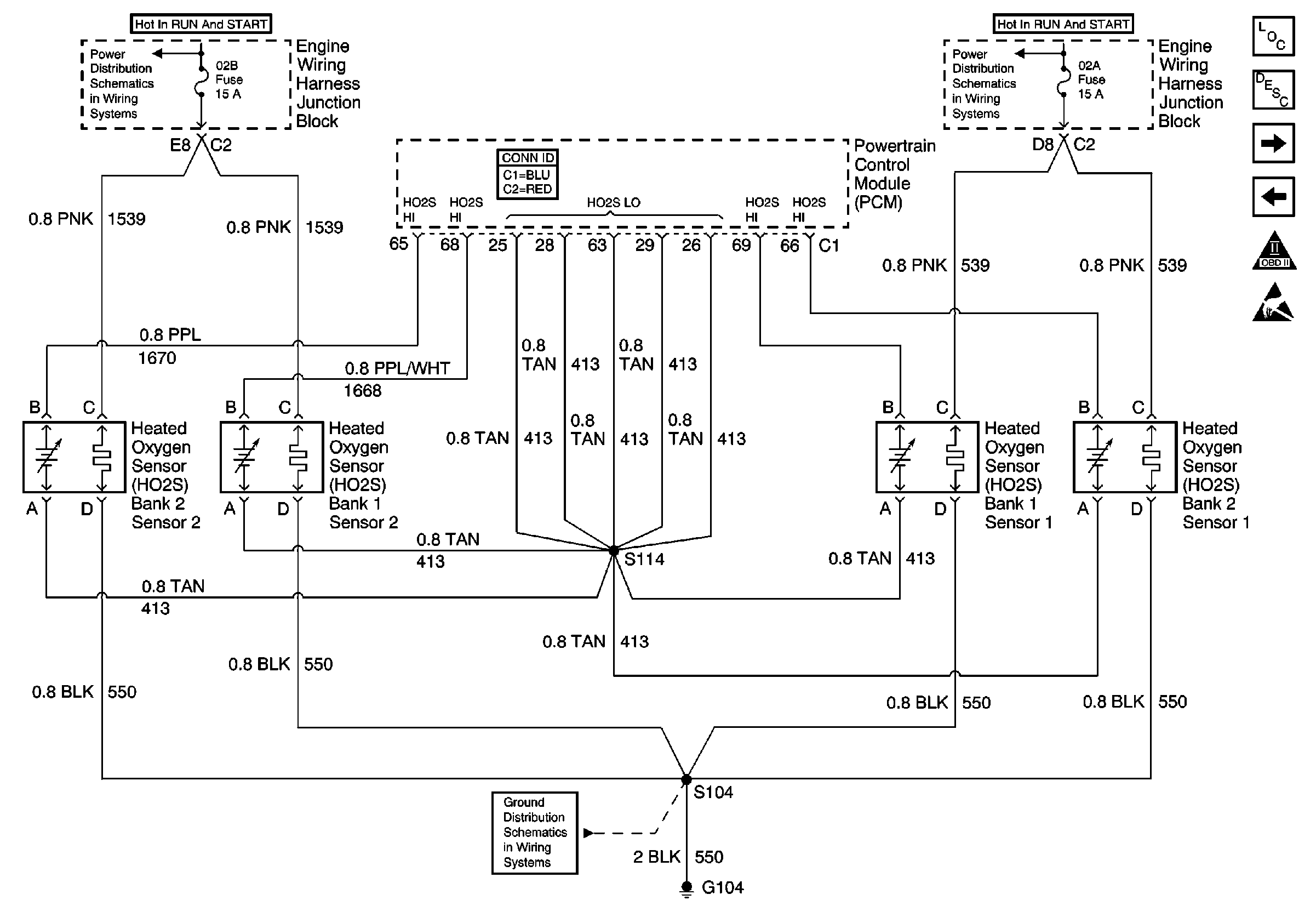
05 8.1 02 Sensor Wiring Diagram
I bought a new truck a few weeks ago from a dealer and after driving it a few days of course the check engine light comes on. The 3500 HD didnt have them along with a few suburbans.

02 Sensor Wiring Diagram Novocom Top
800 x 600 px source.

05 8.1 02 sensor wiring diagram. Describe the meaning of the SD in diagram component T. The first element is symbol that indicate electric component in the circuit. 2000 Honda Accord O2 Sensor Wiring Diagram 2005 Accord O2 Wiring Wiring Diagram Autovehicle.
2000 Honda Accord O2 Sensor Wiring Diagram wiring diagram is a simplified all right pictorial representation of an electrical circuit. Recognize Wiring Diagram Symbols. If playback doesnt begin shortly try.
Im the original owner. Cam and crank sensors have a built-in internal voltage regulator specifically so they can be used with a variety of input voltage signals. The other thing which you will come across a circuit diagram could be traces.
Describe the meaning of the C13 in the diagram component Q. To test set the multimeter to resistance mode and use it to probe and figure out which wires register a resistance usually 4-6 . There are two things which are going to be present in almost any O2 Sensor Wiring Diagram Chevy.
Ok I have a 2001 Silverado 81 4x4 with the Allison transmission. GM uses the same cam sensor with both 5v and 12v signals depending on application. The common aspects in a wiring diagram are ground power supply wire and also connection output gadgets buttons resistors reasoning entrance lights and.
These are checked for accuracy and are all redrawn into a consistent format for easy use. All system wiring diagrams are available in black and white format and may be. O2 sensor bank 1 sensor 2 wiring.
A circuit is usually composed by many components. Describe and identify the diagram component U. Oxygen Sensor Wiring Colour Code Guide NUMBER OF WIRES ON SENSOR MAN SENSOR BRAND 1 2 3 4 FUNCTION GM Delphi I violet violet pink violet violet pink SIGNAL EARTH.
UNDERSTANDING TOYOTA WIRING DIAGRAMS WORKSHEET 1 1. How to test a MAF Sensor using a basic multimeter without having to look up a wiring diagram. Bore size is 902 mm 3552 in and stroke is 1058 mm 4165 in identical to the 54 l v8.
So that question is SOLVED once and for all. The ford modular engine is ford motor companys overhead camshaft ohc v8 and v10 gasoline powered small block engine family. THROTTLE POSITION SENSOR explanation for wiring diagram troubleshooting and simplify tutorial.
Describe the meaning of the 2 in diagram component S. There are just two things that will be present in almost any 4 Wire Oxygen Sensor Wiring Diagram. During the safety inspection I was failed for missing o2 sensors.
Describe the meaning of the G-W in diagram component R. Determine the heater wires. To use the LS2 sensor you just need to feed it input voltage on pin A.
Oxygen Sensor Wiring Diagram Wiring Diagram Collection Koreasee size. Ford V10 Oil Diagram Reading Industrial Wiring Diagrams. The missing sensors are the downstream sensors.
To check out a wiring diagram first you have to understand what fundamental aspects are consisted of in a wiring diagram and also which pictorial symbols are used to represent them. I check the sensor and its not even plugged in. This should be done first.
If you liked this video you may find these other videos useful. Right here are several of the top drawings we obtain from different sources we hope these photos will certainly work to you and ideally really pertinent to what you desire concerning the Oxygen Sensor Wiring Color Codes is. V 6 Engine Diagram Basic Electrical Wiring Theory.
Mitchell1 R obtains wiring diagrams and technical service bulletins containing wiring diagram changes from the domestic and import manufacturers. Theres always one on the intake manifold working its way down to catalytic convertor is the oxygen sensor 1 heater circuitpre cat conv signal while terminal 25 is oxygen sensor. I scan the code and it says no activity bank 1 sensor 2.
It shows the components of the circuit as simplified shapes and the faculty and signal connections amongst the devices. Aug 28 2015 1242am. These wires serve to heat up the O2 sensor to bring it up to operating temperature via a resistance-based heating element.
Another thing that you will locate a circuit diagram could be traces. A circuit is generally composed by various components. The first component is symbol that indicate electric element in the circuit.
I have read a few blogs that claim the truck wasnt manufactured with them. The ABS light is also on but thats not my concern right now.

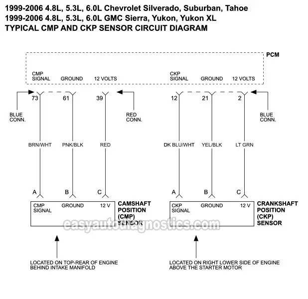
Cmp And Ckp Sensor Circuit Diagram 1999 2006 V8 Silverado Sierra Suburban Tahoe Yukon

New Free Vehicle Wiring Diagrams Pdf Diagram Wiringdiagram Diagramming Diagramm Visuals Visualisation Graphical Check More At Https Thebrontes Co Free
Silveradosierra Com Crank Sensor Wiring Issues Electrical Page 2
2021 Test For 2003 Chevrolet Silverado Cam Sensor Connection Using The Ecm Wiring Diagram

02 Sensor Wiring Diagram Novocom Top

Download Harley Davidson 2018 Wiring Circuit Diagrams Pdf

Hyundai Accent 98 Mfi Control System

02 Sensor Wiring Diagram Novocom Top

02 Sensor Wiring Diagram Novocom Top

02 Sensor Wiring Diagram Novocom Top

02 Sensor Wiring Diagram Novocom Top

Chevrolet Captiva Electrical Wiring Diagrams Free Downloads Chevrolet Captiva Electrical Wiring Diagram Captiva

Wiring Diagram Ecu 2kd Ftv Throttle Systems Engineering Wiring Diagram Systems Engineering Ecu


