02 Rodeo Camshaft Sensor Replacement Connector Wiring Diagram
Remember the CMP sensor must remain connected to its engine wiring harness connector. Describe the meaning of the 2 in diagram component S.

Diagram Mazda 6 Wiring Diagram En Full Version Hd Quality Diagram En Diagramman Prolococusanese It
Click on blue component numbers to see.

02 rodeo camshaft sensor replacement connector wiring diagram. UNDERSTANDING TOYOTA WIRING DIAGRAMS WORKSHEET 1 1. Ad One Stop Shop For Connectors. To replace it with your new Camshaft Sensor Put the Camshaft Sensor in where you took out your Old oneReplace the Retaining Screw Tighten up Good And SnugPut the Wiring connector back on the Sensor and Your Done.
Describe the meaning of the SD in diagram component T. It is terminal 3. The GRN wire is the signal wire that transmits the camshaft position sensor signal to the PCM and is the one labeled with the letter B in the photo.
10 SPECIAL TOOLS WIRINGTERMINAL. GM Low Coolant Sensor and Washer Pump Repair Connector 1580 1199. Connect the red multimeter test lead to the green GRN wire of the 3-wire connector.
Describe and identify the diagram component U. Connect a VAG 159819 test box to the ECM harness connector. Describe the meaning of the C13 in the diagram component Q.
15 DESCRIPTION AND OPERATION INTRODUCTION Chrysler wiring diagrams are designed to provide information regarding the vehicles wiring content. 57 FREE Shipping on eligible orders. Here is a guide to help you get the job done.
I accidently sheared the wires to the camshaft position sensor connector. TERMINALCONNECTOR REPAIR-MOLEX CONNECTORS. Audi A4 and Sedans 1999-05 ECT Sensor Repair Guide.
Which has different color code of wires. To be honest this is a quick and simple DIY but it is a pain in the butt the first time you do it. GM Single Wire O2 Sensor Repair Connector Pigtail 745 499.
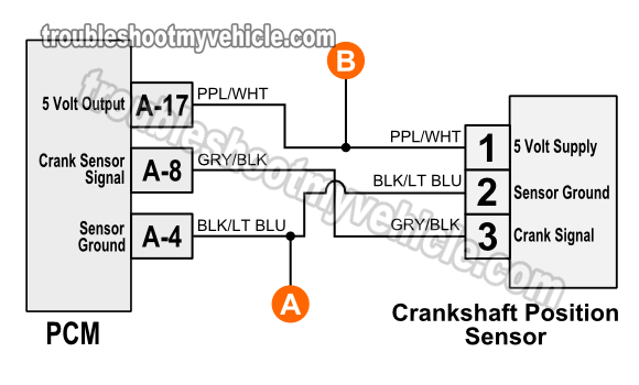
Terminal 2 is Black and white wire from PCM terminal 16 cam position sensor. The wires tore out from the connector. Kia Sephia Rio Spectra Optima 1998-2006.
While replacing the spark plugs and coils at the rear bank. Check the CKP sensor shielding for continuity by connecting a DMM between terminal 3 and engine ground GND. With the ignition ON and the engine OFF measure the voltage between sensor harness connector VPWR and PWR GND terminals refer to the accompanying illustration.
This will get your job doneLet me know Please how My Solutioninstructions have Helped you. Here are wiring diagrams. N52 crankshaft sensor wiring diagram.
Detach the sensor connector and install jumper wires from the power and ground terminals of the sensor connector to the wiring harness. How to Replace Broken Wire Harness Connectors. Jun 22 To utilise the existing LS1 harness and LS1 computer the simplest way is to convert the new block back to LS2 spec.
Without this critical feedback the ECU will not provide ignition spark to the coils and spark plugs. I replaced the connector with one from a JY. E9f297 N52 Crankshaft Sensor Wiring Diagram Wiring Resources P0335 is crankshaft sensor circuit.
Find out how to access AutoZones Engine Coolant Temperature ECT Sensor Repair Guide for Audi Cars 1999-05. GM Coolant Sensor Knock Sensor Repair Pigtail 875 699. Find out how to access AutoZones Wiring Diagrams Repair Guide for Toyota Pick-ups Land Cruiser and 4 Runner 1997-00.
Knock Cam Camshaft Sensor Extension Wiring Harness LS1LS6 to LS2LS3 sensor. 11 WIRING REPAIR. Isuzu Rodeo Ls 4wd Workshop Manual V6-32L 1998 Isuzu Rodeo 2wd Workshop Manual L4-2559cc 26L SOHC 4ZE1 1991 Isuzu - Rodeo - Wiring Diagram - 2000 - 2000.
Meets The EU RoHS Directive 201165EU Claim. Ad One Stop Shop For Connectors. Only 4 left in stock - order soon.
Describe the meaning of the G-W in diagram component R. Terminal 1 is Black wire to ground joined with other sensors. 10 TERMINALCONNECTOR REPAIRTHOMAS AND BETTS CONNECTORS.
Meets The EU RoHS Directive 201165EU Claim. Here are the wiring diagrams and camshaft sensor location. With the ignition OFF disconnect the CMP sensor.
The DMM should show a maximum. If the reading is greater than 105 volts the power circuit to the sensor is okay. Camshaft Position Sensor Testing Three-Wire Sensors.
CRANKSHAFT POSITION SENSOR CONNECTOR With one of the smallest and most easily damaged connectors on the 05-06 ZX6R Wiring Harness the Crankshaft Position Sensor sends information regarding the location of the crankshaft in its rotation. 2007 vw beetle when replacing rpm camshaft sensor 2 of the 3 wires on the engine harness side of the connector broke off. The vehicle is a 2007 Toyota Sienna with the 35L V6.
If the specified value is obtained check the wiring for continuity or short between crankshaft position sensor and ECM using a wiring diagram. I used this method to get prongs out of the. Step 1 Inspect your new block.

Diagram Gm Stereo Wiring Diagram Full Version Hd Quality Wiring Diagram Diagramman Prolococusanese It
Diagram Mustang Sensor Diagram Full Version Hd Quality Sensor Diagram Diagrammoi Prolococusanese It

15 Map Sensor Connector Wiring Diagram Engine Engine Diagram Wiringg Net Map Sensor Engine Diagram Wiring Diagram
Diagram Yamaha Fj1200 Wiring Diagram Full Version Hd Quality Wiring Diagram Tvdiagram Segretariatosocialelatina It

Diagram Pi 4 Wire Color Diagram Full Version Hd Quality Color Diagram Imdiagram Segretariatosocialelatina It
Diagram Gm Coil Pack Wiring Diagram Full Version Hd Quality Wiring Diagram Diagramman Prolococusanese It

6 Wire Oxygen Sensor Wiring Diagram Novocom Top
Diagram Camshaft Position Sensor Wiring Diagram Full Version Hd Quality Wiring Diagram Tvdiagram Segretariatosocialelatina It

Diagram Usb Cable Wire Diagram Full Version Hd Quality Wire Diagram Diagramman Prolococusanese It

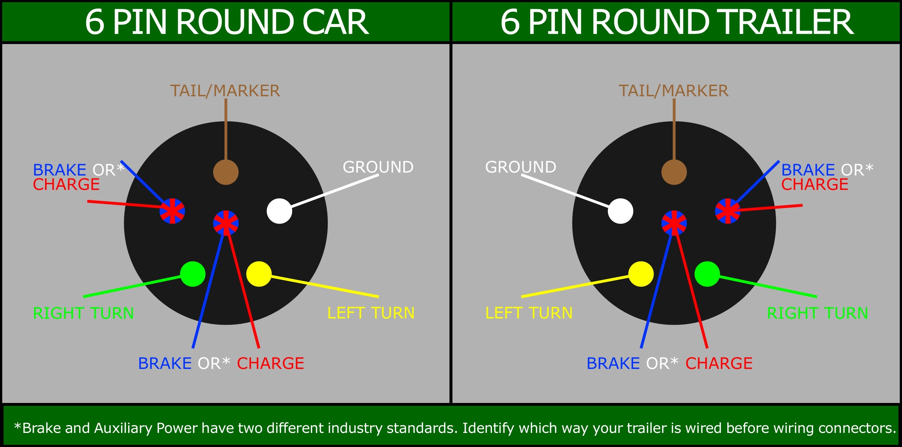
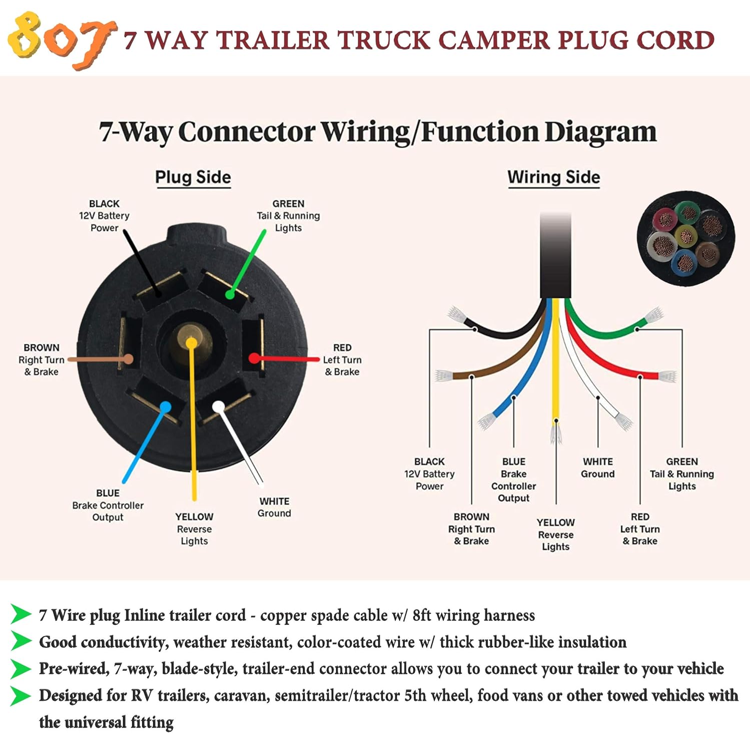
Diagram Simi Trailer 7 Pin Wire Diagram Full Version Hd Quality Wire Diagram Imdiagram Amicideidisabilionlus It

6 Wire Oxygen Sensor Wiring Diagram Novocom Top

Diagram O2 Sensor Wiring Diagram Chevy Full Version Hd Quality Diagram Chevy Lendiagram Amicideidisabilionlus It

Diagram 95 Gsr Ecu Wire Diagram Full Version Hd Quality Wire Diagram Diagrammoi Prolococusanese It

6 Wire Oxygen Sensor Wiring Diagram Novocom Top

Diagram 3 9 Liter Dodge Engine Diagram Fuel Sensor Full Version Hd Quality Fuel Sensor Emrdiagram Amicideidisabilionlus It

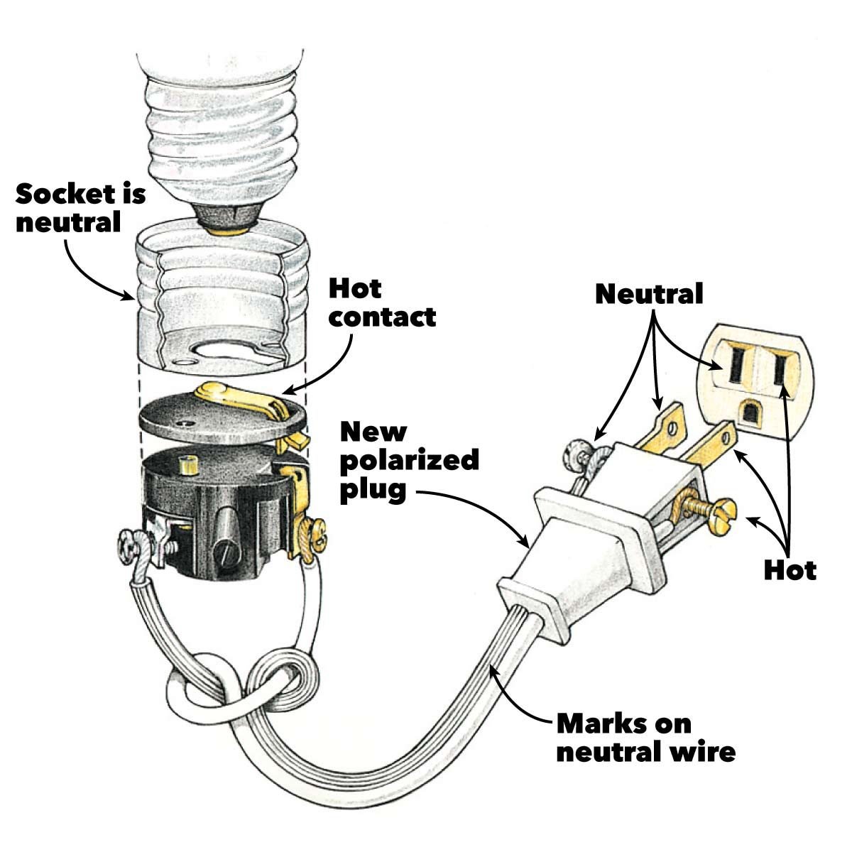
Diagram Auxiliary Cord Wiring Diagram Full Version Hd Quality Wiring Diagram Diagrammar Prolococusanese It


