Illuminator Driving Lights Wiring Diagram
Connect one BLACK lead to the vehicle ground and to the relay terminal labeled 86. 1 Yellow Dash Illumination from park lights 2 Black Negative 3 Blue Switch to Output - to relay trigger 4 Red Switch 2 Input - from high beam positive 5 White Switch 1 Output - driving lights 6 Green Switch 1 Input - from vehicle ignition 7 Not Used NA 8 Not Used NA Fig 7.

Wiring Diagram For Kings Driving Lights
The last end of the adaptor White T.

Illuminator driving lights wiring diagram. It shows the components of the circuit as simplified shapes and the capacity and signal connections between the devices. Locate the bracket in a suitable position using the M10 x 35mm bolt. Badlands Illuminator Wiring Diagram wiring diagram is a simplified suitable pictorial representation of an electrical circuit.
EPAuto LED Light Bar Wiring Harness Kit 12V 40A RelayFuseON-OFF Switch. Power CCT Heavy wire Battery Fuse Relay Pin 87 Relay Pin 30 Driving Lights Chassis Ground Switch CCT Light wire Headlight Common Pin Switch Relay Pin 85 Relay Pin 86 Headlight High Beam Pin. Insert the adapter back in-line with the headlight and connect to the wiring harness.
Its easy really. Insert the in-line fuse back into the socket. Driving Light Wiring Diagrams Negative And Positive Switching pertaining to How To Wire Up Driving Lights Diagram image size.
Door Locks Page A-4 5. Typical 4wd steering configurations a simple overview of crossover steering v link steering re circulating ball and tie rod rack and pinion and double crossover steering systems found on 4x4 solid axle and independent axle setups. Rear Window Defogger Page A-1 2.
The other end of the piggy back adaptor will then connect to the back of your high beam globe. 8 Pin connector wiring diagram switches side 1. Illuminated toggle switch wiring diagram.
Route the RED WHITE wires from the lamps to the relay. The exterior lighting of the F30 is mainly based on the latest BMW models. Jun 15 A quick guide to installing your Illuminator Wiring Harness for Illuminator 9 Round Driving Lights or LED Lightbars.
Connect the YELLOW wire to the yellow switch wire terminal and to the relay terminal labeled 85. Install the driving lights onto a suitable mounting surface 2. This is a much more painful and involved process.
There has to be a more simple way to do this. With bi-xenon headlights constant dipped and parking lights are carried out on. MOUNT THE LIGHTS 1.
Looking over the wiring diagrams it looks like the only solution is to by-pass the ECU and tap in at the hilo switch in the cabin. Equipment can be ordered bi-xenon headlights SA 522. Remove the nyloc nut and M10 washer from M10 x 35mm bolt attached to the bottom of mounting bracket 3.
Pictured is my wiring diagram for installing two fog lights with fuses a switch and a relay. Illuminator Driving Lights Wiring Diagram wiring diagram is a simplified enjoyable pictorial representation of an electrical circuit. It shows the components of the circuit as simplified shapes and the power and signal friends between the devices.
Looking at page LI-65 it seems that the wire Im looking for is HU-11 on the headlight dimmer switch assembly. Wiring diagram for lightforce driving lights. F30 is equipped with halogen headlights as standard.
Understanding Diagrams Page U-1 Lighting Systems 1. Fitted with four genuine OSRAM LEDs in each light and a tough die-cast alloy housing with in-built passive cooling fins these lights. Whenever your parking lamps are on and the toggle is on youre driving.
Draw a diagram on plain white paper with wire gauge noted and colors identified. Before cutting any wire a good diagram is in order. Then run the acc side of your toggle to the 86 terminal on the relay.
Automatic Light Turn-off Page L-4 5. Power Mirrors Page A-3 4. Daytime Running Lights Page L-5 Accessories Systems 1.
Driving Lights Diagram Wiring Schematic Diagram 32 Beamsys Co Adventure Kings Illuminator Led Driving Light Wiring For those of you that have damaged tpms sensors or none at all and want to get rid of the tpms light on the dash theres a good guide here but that only mutes the light the tpms ecu is still active. This wiring diagram will stay with the car so make it neat and easily readable. Using a flat-head screw driver pop out the terminals from both the socket and the plug and reinsert them like so.
It is recommended that the base area of the mounting bracket is totally supported 4. Clock Cig Lighter Page A-5 6. Remove your high beam plug from the rear of the headlight and connect it to the piggy back adaptor supplied.
Each of our carling rocker switch bodies have the generic each wiring diagram is downloadable and printable for use during your installation. I have gone with text as many people have trouble with electrical diagrams. If halogen headlights are installed the headlight range is manually adjusted.
Theyre perfect for using as reverse lights side or rear-mounted camping lights or even for pointing off at an angle on your bullbar to add extra front-facing light spread. Each component must be labeled. Adventure Kings Illuminator Led Light Bar Wiring Harness Trade Me Diy Led Light Bar Fuse Box 1 Wiring Diagram Source Kings 20 Slim Line Led Light Bar Illuminator.
Test the lights they will now work with a. Tap into the parking lamps 12v wire from somewhere in the dash or an non dimming illumination wire in your dash to use as the positive side of your toggle switch. Connect the RED WHITE wire to the lamp terminals and to the relay terminal labeled 87.
Stop Lights Page L-3 4. Headlights Page L-1 2. Diagram 2 wire toggle switch diagram full version hd quality.
Power Windows Page A-2 3. Turnsignals Hazard Page L-2 3. Wiring light bar rocker switch how to wire a light bar to a toggle.

Unique Car Electrical Diagram Diagram Wiringdiagram Diagramming Diagramm Visuals Visualisation Graphical Check Mor Jeep Cj7 1979 Jeep Cj7 Wiring Diagram

Lovely Wiring Diagram Vespa Excel 150 Diagrams Digramssample Diagramimages Wiringdiagramsample Wiringdiagram Check More At Https Nostoc Co Wiring Diagram

Https Www 4x4community Co Za Forum Attachment Php Attachmentid 458661 D 1503600621 Electrical Diagram Electrical Circuit Diagram Wiring Diagram

Wiring Diagram Driving Lights

4 Pin Relay Wiring Diagram Lights Relay Electricity Automotive Electrical
Vw Amarok Spot Light Fitting Motorspark
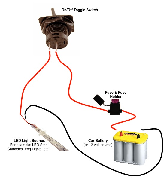
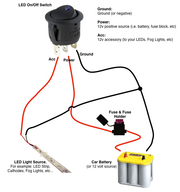
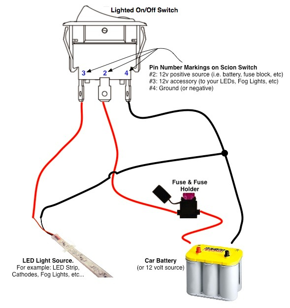
On Off Switch Led Rocker Switch Wiring Diagrams Oznium

Wiring Diagram For Lightforce Driving Lights

On Off Switch Led Rocker Switch Wiring Diagrams Oznium

17 Car Horn Relay Wiring Diagram Auto Mecanica Fiacao Eletrica Auto

Xrm6 Engine Diagram Uk

Wiring Diagram Driving Lights
On Off Switch Led Rocker Switch Wiring Diagrams Oznium

Narva Wiring Diagram Wiring Diagram Relay Diagram

G3ye9p6q2ou4ym
How To Tap Into High Beam Wire Mazdas247

Pin On Shawn S Shit

Wiring Diagram Driving Lights